
I was sorting though some old junk when I found an old but unused laptop battery pack for the 1st Generation DER laptop (Lenovo s10e). It would have been a waste to chuck out an unused battery pack, but the laptop it belonged to was more than obsolete now (and we didn't have any of them left). So I thought maybe I could use the cells inside for something. The size, shape, voltage and capacity certainly suggested that it contained six 18650 lithium cells. After cracking the case apart, it revealed six high quality Panasonic NCR18650 cells rated at 10.73Wh (2900mAh).
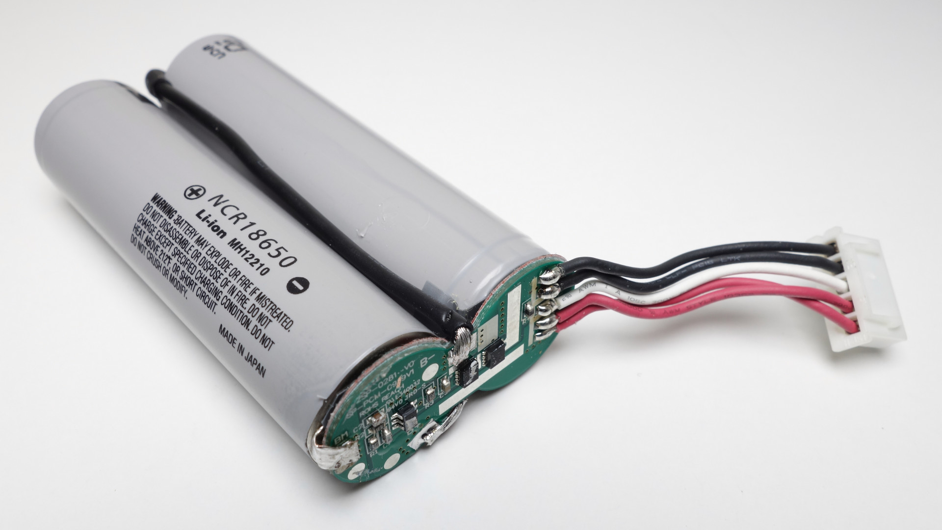
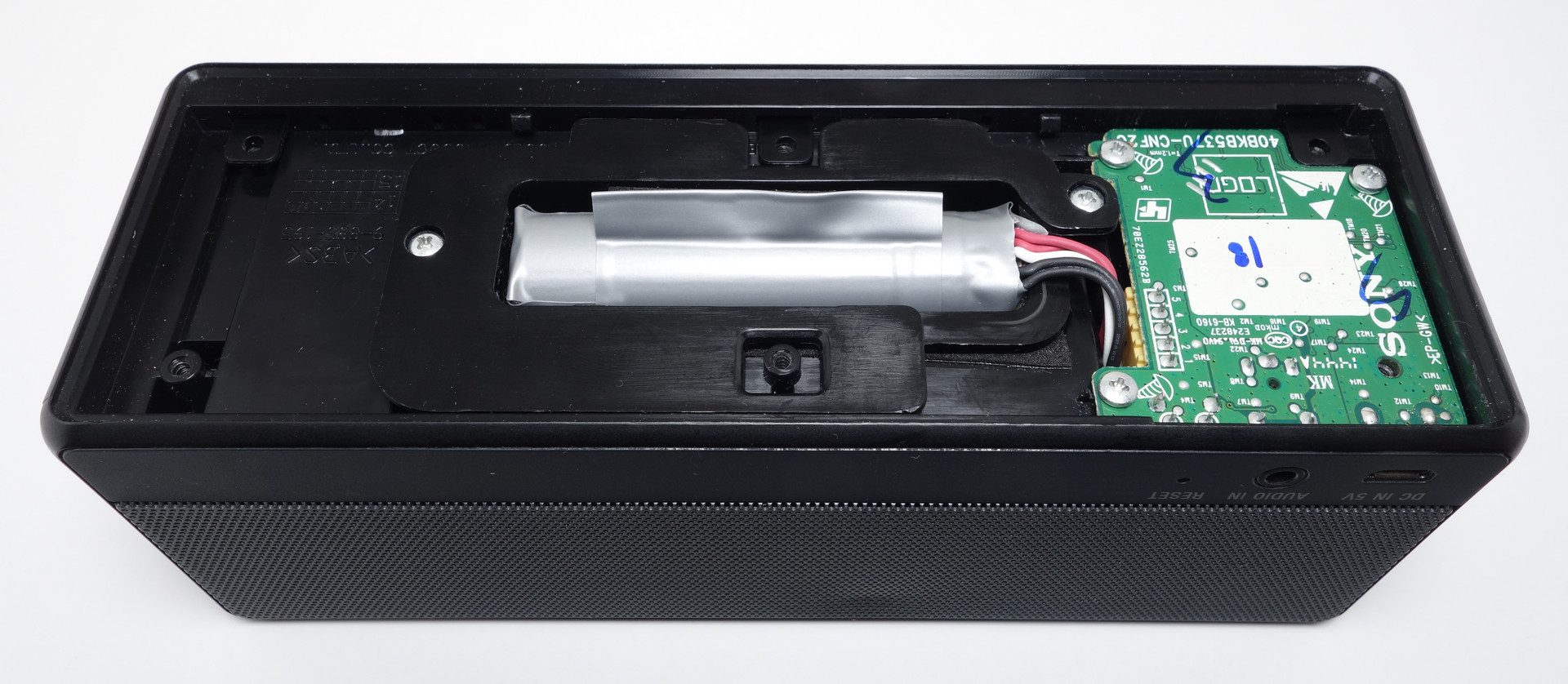
So then I was thinking what products of mine used 18650 cells. The two things that came to mind was my Sony SRS-X3 speakers and Led Lenser M7RX torch. I remember when I first disassembled my SRS-X3, I was disappointed to find a Chinese battery pack (ST-01) of dubious origins (Huizhou Highpower Technology Co., Ltd) which was only rated at 16.28Wh (two 2200mAh 18650 cells). At the time, I wasn't concerned with the battery life, so I left the original batteries in. So with the Panasonic RCR18650 cells, I'm expecting at least a 30% increase in battery life. The M7RX also comes with an 8.14Wh (2200mAh) protected cell. I can only assume manufacturers use the 8.14Wh cells to cut costs. I had already picked up an EagleTac 18650 3400mAh protected cell (Panasonic cell) for my M7RX, but you can never have enough spare batteries!
If you are replacing your device with new batteries, I suggest getting the Panasonic NCR18650B cells, rated at 12.58Wh (3400mAh).
Enough talk... here are the instructions for replacing the battery pack in the Sony SRS-X3. We will be de-soldering the protection circuit from the original battery pack and soldering it to the new cells.
Required Tools/Materials
- Something thin and flat, such as a flat head screwdriver
- A Phillips #1 screwdriver (J1 if you have one)
- Soldering iron and solder
- Electrical tape or similar
- Two 8cm lengths of hookup wire capable of at least a 3A load
- A small length of metal or wire (braided solder wick works too)
Recommended Tools/Materials
- Heatshrink
- Flux pen
Steps
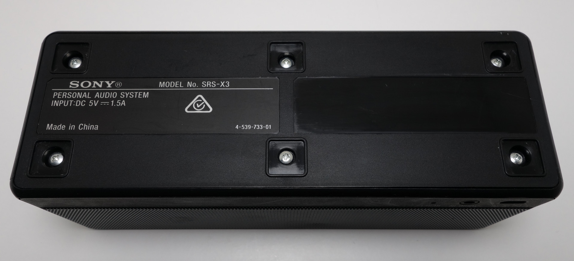
- Peel the 6 foam pads off the bottom of the speaker
- Use something thin and flat to peel, such as a flathead screwdriver
- Peel from the corner
- Peel slowly
- Remove the 6 silver screws and remove the bottom cover
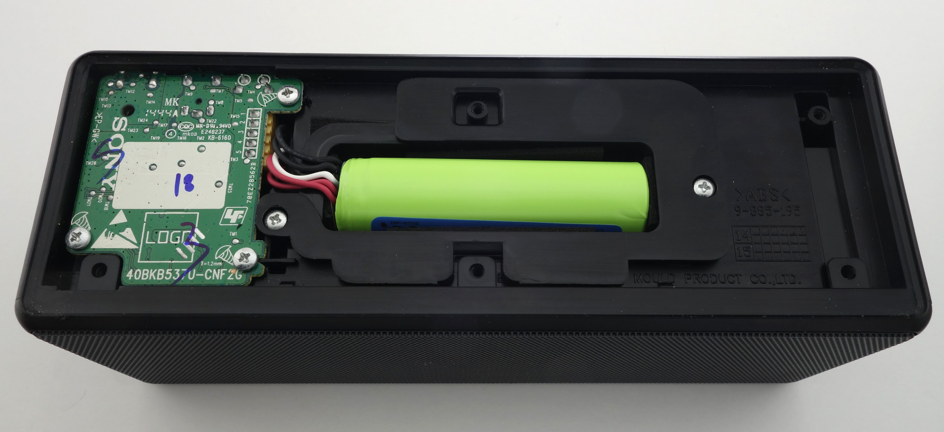
- Remove the 5 silver screws holding the circuit board and battery pack in place
- Remove the front bezel by pushing the 3 retaining clips out (towards the front of the device)
- Remove the 8 screws around the two speakers
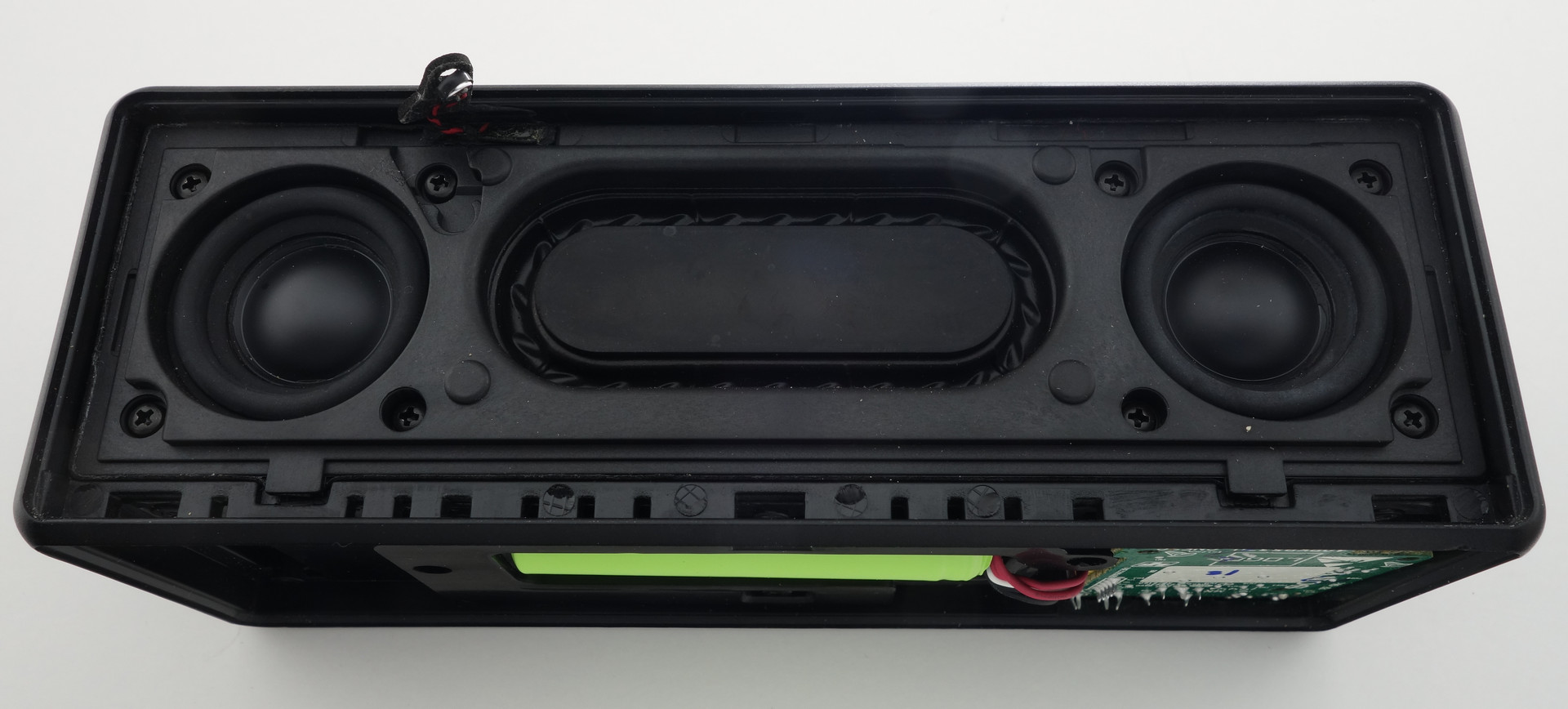
- Pry out the piece of plastic holding the two speakers in place taking care not to pull on the microphone
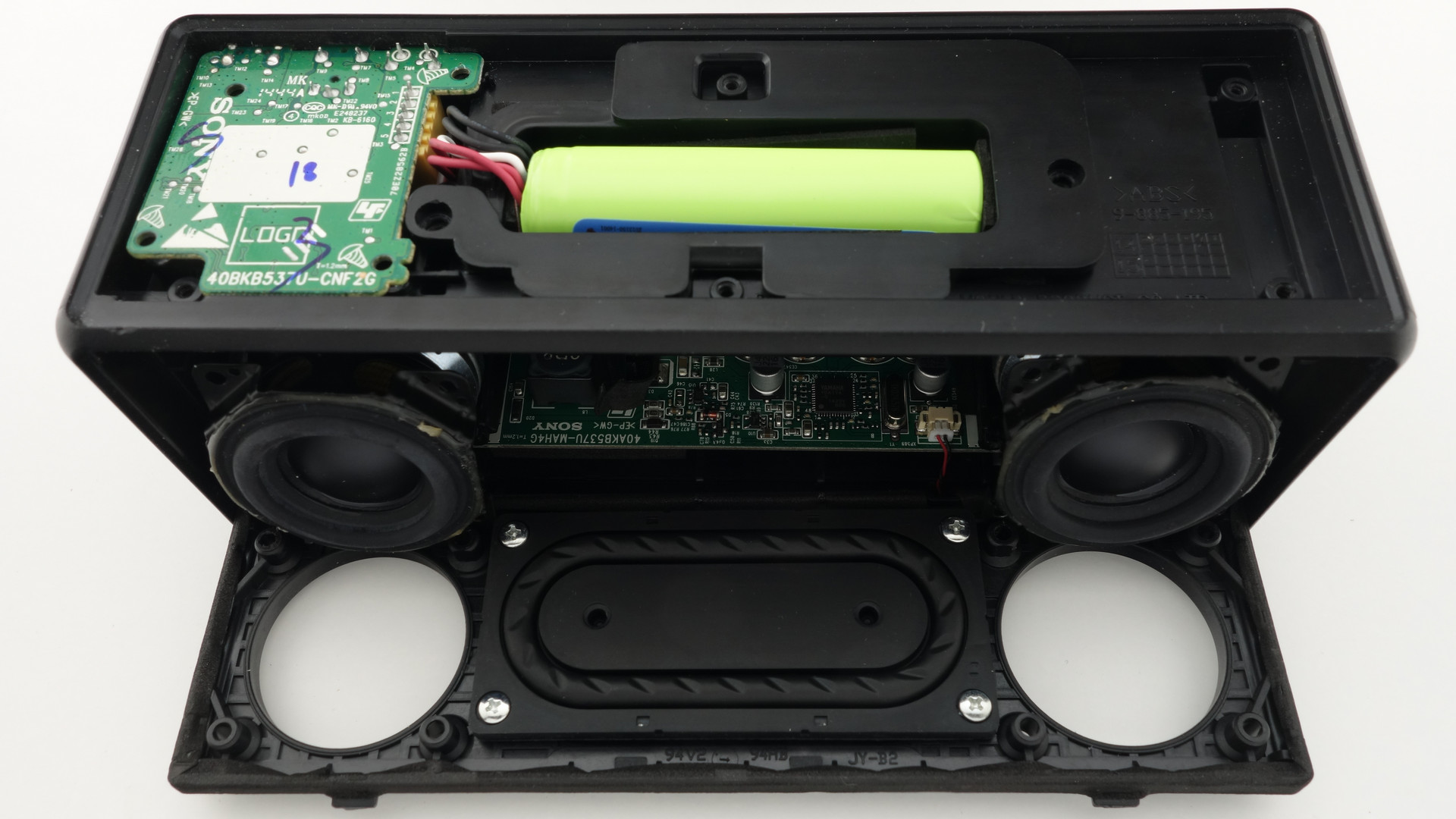
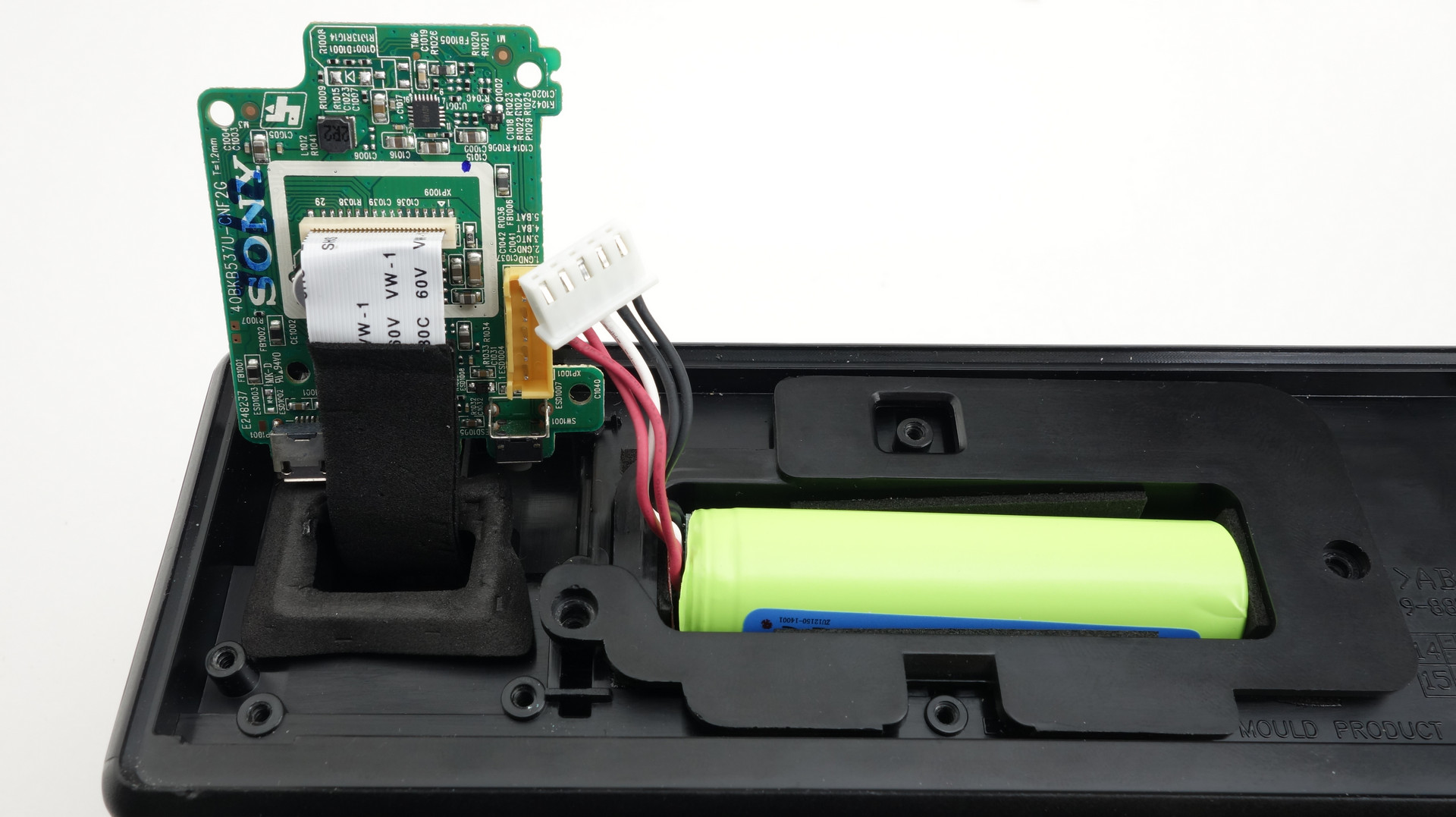
- Lift the daughter board (connect to the battery) out by levering it up (about 30 degrees) from the front of the unit. Then pull the board away from the rear of the unit, dislodging the rear IO.
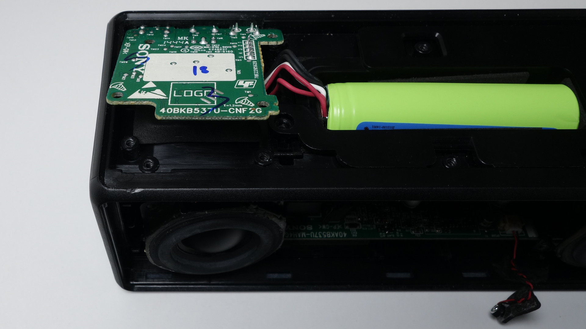
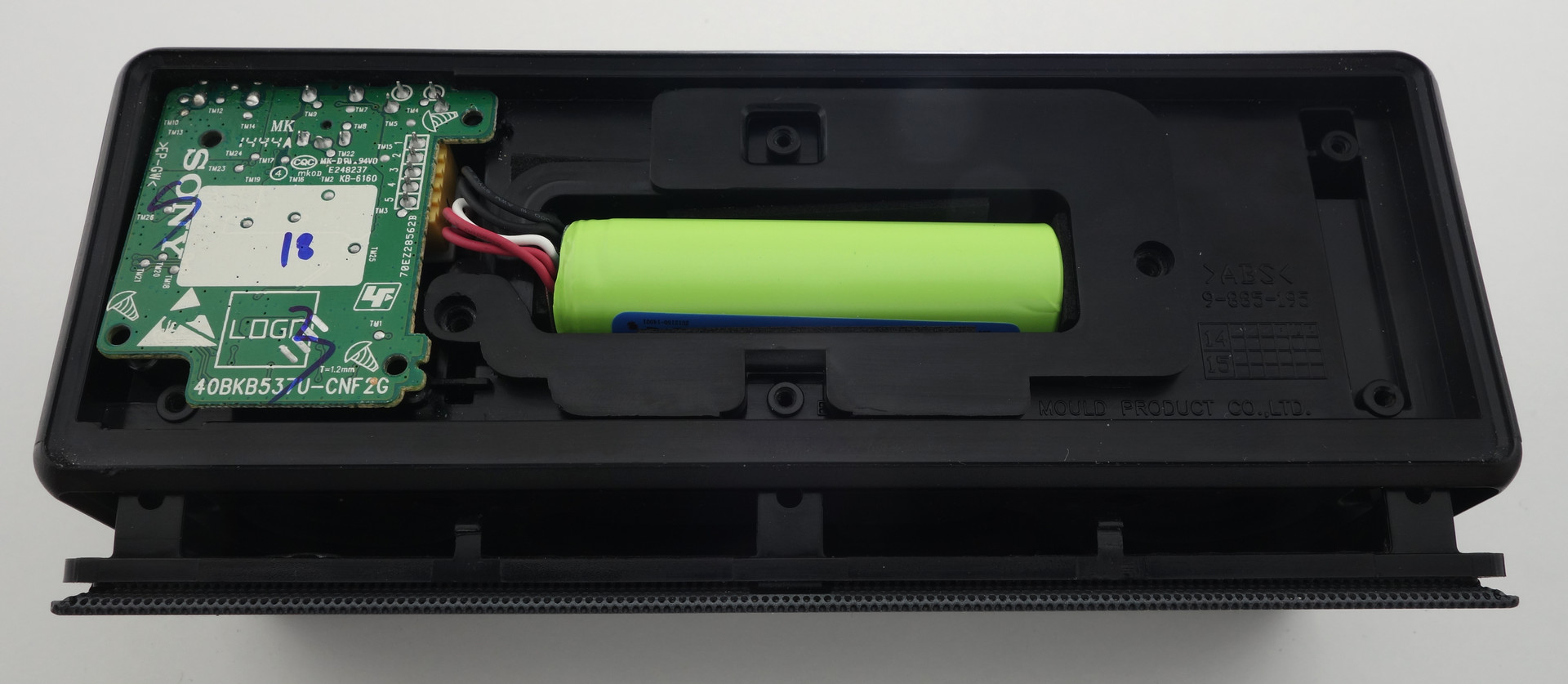
- Pull the battery holder out of the unit and disconnect it from the daughter board
- Remove the battery pack from the battery holder by wiggling it left and right. Do not pull on the wires with too much force.
- Cut away the plastic wrapped around the cells and remove the red protective cardboard at both ends of the batteries
- De-solder the existing connections to
B+,B-andBMand detach the circuit board from the cells -
Prepare your new cells
Be careful not to short anything! We don't want exploding batteries.
- Connect the two cells in series
- Glue or tape the two cells together
- Attach a wire to the
+veand-veends of the battery and run them down opposite sides of the battery to the other end
- Solder the battery protection circuit board to the new set of batteries
- Soldering onto the battery casing is generally a bad idea due to the heat, so if you must solder onto the cell itself:
- Use flux
- Use small amounts of solder
- Solder extremely fast!
- Cool the battery down as soon as the solder joint is made (use a sponge)
- The circuit board should rest above the bridge joining the two cells
- Make sure nothing from the battery contacts the bottom of the circuit board
- The
B+terminal connects to the positive end of the battery through the length of wire - The
B-terminal connects to the negative end of the battery through the length of wire - The
BMterminal connects to the bridge connecting the two batteries in series through that length of metal or wire- The
BMconnection is used to monitor both cells individually. As no two cells are perfectly identical in capacity and state of charge, the charge circuiry is able to monitor and charge cells individually instead of as a pack. This prevents over-charging/over-discharging of individual cells and optmises the capacity of the battery pack as a whole. This is known as battery balancing.
- The
- Soldering onto the battery casing is generally a bad idea due to the heat, so if you must solder onto the cell itself:
- Tape the circuit to the batteries
- Place battery pack into battery holder
- Connect the battery pack back onto the daughter board
- Feed the flat flex (connecting the daughter board to the main board) back into the main compartment through the cutout and fit the daughter board back into position by sticking the IO ports into their cutouts first.
- You will need to pull out the left speaker to get the flat flex back into the compartment. There is no need to disconnect the speaker.
- Replace the left speaker with the speaker connections oriented to the left of the device.
- Ensure both speakers are resting on their mounting posts
- Replace the piece of plastic holding the speakers in place, ensuring the microphone is on the outside of the device.
- Screw in the 8 black screws holding that piece in place
- Place the microphone back in its cutout
- Replace the front speaker grill
- Screw in the 5 silver screws holding the daughter board and battery holder
- Replace the bottom cover and screw in the 6 silver screws
- Stick the foam pads back onto the bottom of the speaker

Results
A dead battery takes just over 5 hours to fully charge with a 5V 2.1A charger.
I haven't done any scientific tests, but with casual listening it certainly feels like a larger than 30% capacity improvement. I have doubts that the original cells were actually 16.28Wh. Perhaps they were at very low discharge rates.